
For over 10 years, we have supplied high-performance heat transfer pads to global EV and electronics manufacturers. During this time, we have seen every selection mistake and supplier shortcut that procurement teams often miss. The insights in this guide come straight from our factory floor, not from generic datasheets.
What Is a Thermal Pad for Processor?
Definition and Function
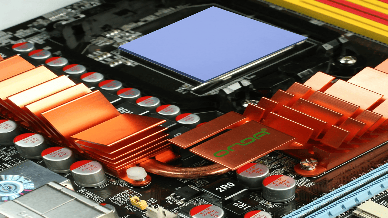
A thermal pad is a soft, pre-formed sheet that conducts heat. You place it directly between a chip (like a CPU or IGBT) and the heat sink. It moves heat away quickly and stays stable over years of use. Unlike liquid paste, thermal pads are mess-free. They need no curing time, making automated assembly simple and reliable.
The Core Role: Filling Micro-Gaps
Microscopic surface imperfections trap air between the processor and heat sink. Because air is a severe thermal insulator (≈ 0.025 W/m·K), a thermal pad must displace this air to create an unbroken thermal path.
- Without pad: Processor → AIR GAP → Heat Sink ❌ (Heat trapped)
- With pad: Processor → THERMAL PAD → Heat Sink ✅ (Heat flows)
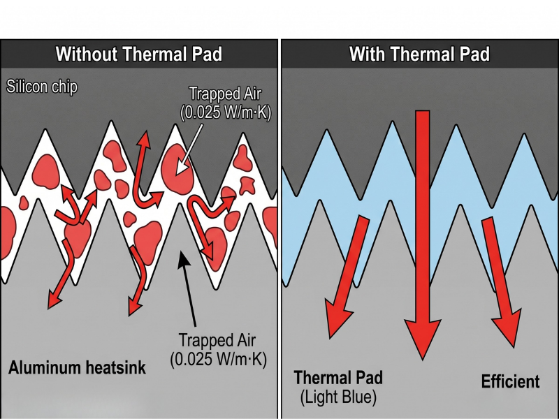
Controlled compression of the pad eliminates these air gaps, minimizing thermal resistance and maximizing component lifespan.
Thermal Pads vs. Other TIMs
Thermal pads are the most production-friendly option for processors. Here is how they compare to alternatives:
| TIM Type | Form | Best For | Limitations |
|---|---|---|---|
| Thermal Pad | Soft, pre-formed sheet | Gaps 0.3–5.0 mm, mass production, automated assembly | Higher thermal resistance than paste at identical conductivity |
| Thermal Paste | Liquid / Grease | Tight gaps (< 0.1 mm) for direct die-to-heatsink contact | Messy, pump-out risk, zero gap-filling capability |
| Thermal Tape | Adhesive film | Lightweight components requiring mechanical bonding | Low conductivity (< 1.0 W/m·K), permanent bond |
| Phase-Change Material (PCM) | Solid (room temp) to fluid | High-performance CPUs/GPUs needing minimal bond line | Higher cost, requires operating heat to reflow |
Specify a thermal pad when:
- The gap exceeds 0.3 mm.
- Your process requires automated, repeatable assembly.
- The application demands electrical insulation.
- Design mandates reworkability for maintenance.
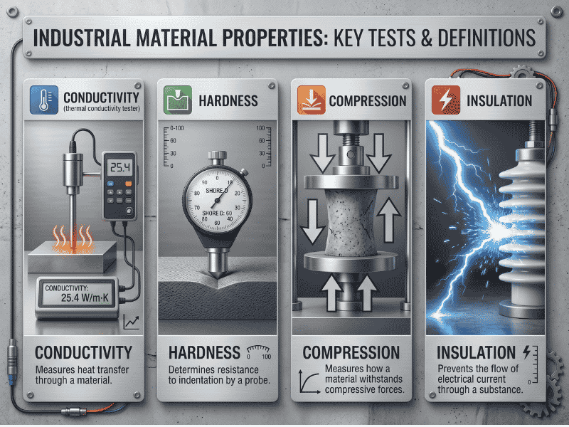
The 4 Key Properties to Specify
While datasheets list numerous metrics, these four dictate thermal performance and assembly safety:
1. Thermal Conductivity (W/m·K)
The rate of heat transfer through the material.
- 1.0–1.5 W/m·K: MCUs, LED drivers, consumer electronics.
- 3.0–6.0 W/m·K: Automotive ECUs, industrial controllers, routers.
- 10–15 W/m·K: High-TDP CPUs, GPUs, IGBTs, 5G base stations.Note: Higher is not universally better. High-conductivity pads are often stiffer, risking component damage under pressure.
2. Hardness (Shore 00)
The standard scale for soft polymers and gels.
- Shore 00 30–50 (Soft): Ideal for fragile dies (BGA); minimizes assembly stress.
- Shore 00 50–70 (Medium): Balanced gap-filling and structural integrity.
- Shore 00 70–90 (Hard): Stiffer; excellent for automated handling but risks cracking sensitive components.
3. Compression Ratio
Determines contact efficiency without crushing the die. A standard 20–40% compression rating indicates that under optimal pressure, a 2.0 mm pad compresses to 1.2–1.6 mm. Achieving this sweet spot prevents board warping while ensuring zero air gaps.
4. Electrical Insulation
Most processor applications require the pad to conduct heat but block electrical current to prevent short circuits. Verify two metrics:
- Dielectric Strength: ≥ 5 kV/mm
- Volume Resistivity: ≥ 10¹² Ω·cm
Types of Thermal Pads for Processor Applications
Specifying the correct thermal pad for processors prevents overheating, assembly bottlenecks, and warranty failures. A pad designed for a 5W router MCU will fail on a 250W server GPU.
This section categorizes thermal pads across four critical axes: base material, conductivity, form factor, and adhesive options, enabling you to draft a precise engineering specification.
Classification by Base Material
The polymer matrix dictates temperature range, outgassing behavior, and unit cost.
- Silicone-Based (Industry Standard):
- Specs: −50°C to +200°C | 1.0–15.0 W/m·K.
- Best For: 80% of applications (CPUs, GPUs, telecom modules, industrial controllers).
- Limitation: Outgassing of low-molecular-weight siloxanes can contaminate optical sensors or relays in sealed environments.
- Non-Silicone (Acrylic/Polyurethane):
- Specs: −40°C to +150°C | 1.5–6.0 W/m·K.
- Best For: Optical equipment, automotive cameras, medical devices, hermetically sealed assemblies.
- Advantage: Zero siloxane outgassing. Higher unit cost.
- Graphite:
- Specs: Anisotropic (In-plane up to 1500 W/m·K; Through-plane 5–20 W/m·K).
- Best For: Heat spreading across flat surfaces (smartphone SoCs, ultrabooks).
- Limitation: Electrically conductive. Requires insulation near exposed circuitry.
- Metal-Based (Indium/Liquid Metal):
- Specs: 25–80 W/m·K.
- Best For: Overclocked CPUs, military radar, HPC servers.
- Limitation: Premium pricing. Indium reacts with aluminum, requiring nickel-plated contact surfaces.
Classification by Thermal Conductivity Tier
Map your processor’s heat load to the correct conductivity tier.
| Tier | Conductivity (W/m·K) | Typical Applications | Hardness (Shore 00) |
|---|---|---|---|
| Entry | 1.2 | Consumer electronics, LED drivers, low-power MCUs | 35–50 |
| Standard | 3 | Routers, network switches, automotive ECUs | 40–55 |
| Mid-Range | 6 | Industrial PCs, mid-range GPUs, 5G boards | 50–65 |
| High-Perf. | 10 | High-TDP CPUs/GPUs, IGBTs, telecom RF amps | 55–70 |
| Premium | 15.0+ | AI/HPC chips, automotive inverters, 800G optics | 60–80 |
Engineering Reality Check: Higher conductivity does not guarantee lower junction temperatures. High-performance pads are stiffer. A 6.0 W/m·K pad achieving 80% surface contact will consistently outperform a 15.0 W/m·K pad achieving only 50% contact due to poor compression.
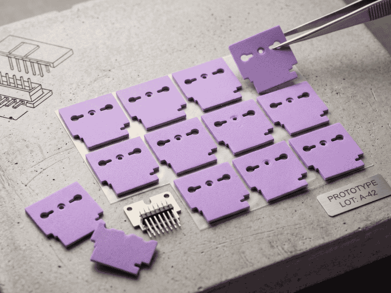
Classification by Form Factor
Delivery format impacts assembly speed and scrap rate.
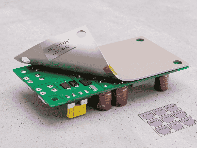
- Standard Sheet Stock: Flat sheets (e.g., 200×400 mm). Lowest cost per m². Ideal for R&D, prototyping, and in-house manual cutting.
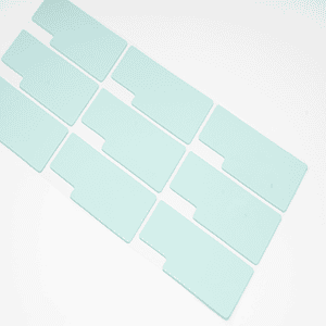
- Custom Die-Cut Pads: Pre-cut to match specific packages (BGA, LGA, QFN). Minimal scrap, consistent thickness, and optimized for automated SMT lines.
- Multi-Cavity Pads: Complex geometries with custom cutouts. Best for multi-chip modules, providing single-piece installation across multiple heat sources to reduce SKU count.
Classification by Adhesive Option
Adhesion determines reworkability and vibration resistance.
- Non-Adhesive (Naturally Tacky): Standard silicone tackiness. Removable without residue. Best for applications requiring field service or prototype iteration.
- Single-Sided PSA (Pressure-Sensitive Adhesive): Holds position during automated handling and resists vibration (ideal for automotive/industrial). Adds minor thermal resistance.
- Double-Sided PSA: Creates a permanent bond, eliminating the need for mechanical fasteners (screws/clips) on lightweight components. Not reworkable.
Drafting the Complete Specification
A professional procurement BOM combines all four axes. Here is an example of a complete specification:
“Silicone-based thermal pad, 6.0 W/m·K, 1.5 mm thick, die-cut 25 × 25 mm, single-sided PSA on heat sink face, Shore 00 hardness 55 ± 5.”
Why this spec works:
- Silicone-based: Broad temperature stability and mainstream pricing.
- 6.0 W/m·K: Matches a typical 30–80W processor thermal load.
- 1.5 mm thick: Fills the engineered gap while allowing a 20–40% compression buffer.
- Die-cut: Ready for automated assembly with zero waste.
- Single-sided PSA: Secures the pad during vibration testing but allows field servicing.
- Shore 00 55: Conforms to the BGA package without applying stress to the die.
How To Select and Apply the Right Thermal Pad
Selecting the correct material is only half the engineering challenge; application determines long-term reliability. This section outlines the standard 6-step assembly workflow and addresses the primary failure mode observed on production floors: compression mismatch.
Step 1: Measure Gap and Surface Area
Never rely on CAD nominal dimensions. Tolerance stack-up frequently alters the final mechanical gap.
- Use a calibrated feeler gauge or digital height gauge (±0.05 mm precision).
- Measure at a minimum of 4 points across the contact zone to detect warping.
- Record the maximum measured gap as your design baseline.
Step 2: Match Thermal Conductivity to TDP
Specify conductivity based on processor Thermal Design Power (TDP), not the highest available datasheet value.
- 1.5–3.0 W/m·K: ≤ 15 W (Low-power MCUs, SoCs)
- 3.0–6.0 W/m·K: 15–65 W (Industrial CPUs, embedded GPUs)
- 6.0–10.0 W/m·K: 65–200 W (Server CPUs, workstation GPUs)
- 10.0–30.0 W/m·K: ≥ 200 W (HPC, AI accelerators, EV inverters)
Step 3: Calculate Pad Thickness (The 20–40% Rule)
Thickness must account for the measured gap plus the required compression allowance to eliminate air voids.
- Formula: Pad Thickness = Measured Gap + 20–40% compression allowance.
- Example: A 1.5 mm measured gap requires a 1.8–2.1 mm pad.
- Never stack multiple thin pads to fill a large gap; multiple interfaces multiply thermal resistance.
Step 4: Surface Preparation
Contaminated surfaces negate high-performance TIM specifications.
- Clean the processor IHS and heat sink with ≥99% isopropyl alcohol (IPA).
- Use only lint-free cloths.
- Inspect under angled light to ensure zero residual flux, oxidation, or machining oils.
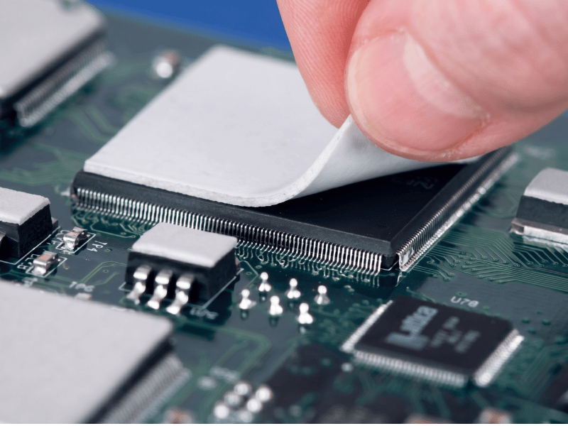
Step 5: Placement and Coverage
Partial coverage generates localized hotspots.
- Remove the protective liner from one side and press the pad onto the colder surface (heat sink) first.
- Ensure full coverage of the heat-generating zone.
- Do not stretch or fold the pad.
Step 6: Torque and Verification
Uneven pressure compromises the thermal interface.
- Tighten heat sink screws in a cross-pattern sequence.
- Apply torque in 2–3 incremental passes using a calibrated torque driver.
- Verify post-assembly gap to confirm the pad reached the engineered 20–40% compression.
The #1 Assembly Failure: Pad Thickness and Compression Mismatch
Field data indicates incorrect pad thickness causes more thermal failures than material degradation. This manifests in two extremes.
Mistake 1: Pad Too Thin (Thermal Failure)
Specifying a 1.5 mm pad for a 1.8 mm actual gap traps 0.3 mm of air. Air has a thermal conductivity of just ~0.025 W/m·K, acting like an insulator. It traps heat, pushes junction temperatures 15–30°C higher than predicted, and forces the processor to throttle.
Mistake 2: Pad Too Thick (Mechanical Failure)
Specifying a 3.0 mm pad for a 2.0 mm gap forces >50% compression. The pad becomes a rigid mechanical load, transmitting heat sink torque directly into the silicon die, causing micro-cracks in fragile components like IGBTs or BGAs.
The 20–40% Compression Sweet Spot
Achieving 20–40% compression guarantees full surface conformity without exceeding safe mechanical stress limits.
| Measured Gap | Recommended Pad Thickness |
|---|---|
| 0.5 mm | 0.6 – 0.7 mm |
| 1.0 mm | 1.2 – 1.4 mm |
| 1.5 mm | 1.8 – 2.1 mm |
| 2.0 mm | 2.4 – 2.8 mm |
| 3.0 mm | 3.6 – 4.2 mm |
The Hardness Trap (Datasheet vs. Reality)
Many pads claim “30% compression” but fail on the assembly line because their Shore 00 hardness exceeds 80. Stiff pads require immense torque to compress, resulting in stripped threads, warped PCBs, or incomplete closure.
The Jiuju Engineering Edge
Solving the compression mismatch requires molecular-level modification. Our 28-engineer R&D team engineered Jiuju’s polymer matrix to solve this exact bottleneck.
- Consistent Softness: We maintain a Shore 00 hardness of 40–60 across our entire product line, from 1.2 W/m·K up to our extreme 30 W/m·K high-performance pads.
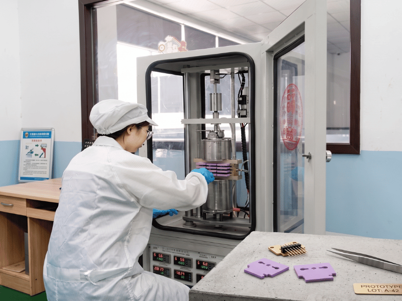
- Verified Performance: Our heat transfer pads compress exactly 20–40% under normal assembly torque. We verify these results using strict ASTM D5470 testing.

- Production Reality: If the Jiuju spec sheet says 30% compression, your assembly line gets exactly 30%. This prevents board stress and removes air gaps.

Conclusion
Choosing a thermal pad seems simple. But every time we investigate a failed processor, we find the same cause. Someone ignored the basic rules in this guide.
When scoping a new design, measure the mechanical gap before specifying conductivity. Applying the 20–40% compression rule prevents both air-gap thermal failures and crushed-die damage. When you evaluate suppliers, look past the basic conductivity number. Always demand the Shore 00 hardness value and the compression curve.
Your Next Step
Require a heat transfer pad engineered for your specific processor application? Jiuju provides:
- Consistent Softness: Shore 00 40–60 hardness across the 1.2–15 W/m·K range.
- Verified Performance: True 20–40% compression at rated assembly torque.
- Traceability: Full QC documentation provided with every batch.
Frequently Asked Questions
Q1: How do I choose the right thermal pad thickness for my processor?
Measure the actual mechanical gap between the processor die (or IHS) and the heat sink baseplate under final assembly torque. Do not rely on nominal CAD values. Select an uncompressed pad thickness that guarantees 20–40% compression. For example, a measured 1.0 mm gap requires a 1.3–1.5 mm pad.
- Too thin: Creates air gaps, leading to immediate thermal failure.
- Too thick: Transfers extreme pressure, resulting in crushed components or PCB warpage.
Q2: My processor is throttling under load. Could the thermal pad be the cause?
Yes. Interface failure is one of the most common causes of processor throttling. If your heat sink and fans are operating to spec but junction temperatures exceed targets, disassemble the unit. The heat transfer pad is the bottleneck if you observe:
- Real compression falling outside the 20–40% sweet spot.
- Visible air voids within the bond line.
- Dry-out (loss of material elasticity).
- Pump-out (material migration away from the heat-generating zone).
Q3: How often should thermal pads be replaced in industrial applications?
Choose a pad with a stable polymer base and a Shore 00 40–60 hardness. If you compress it correctly, the pad will outlast the processor in any sealed industrial unit. Replace it only when you open the hardware for maintenance, chip upgrades, or heat sink adjustments.

