
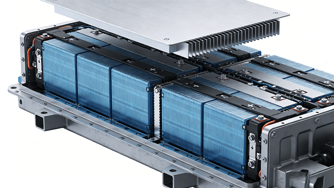
All EV battery packs are engineered to be cool and consistent, but engineers continue to contend with temperature variances, hotspots and battery cells that run hotter than anticipated. These issues, in the majority of cases, are not a result of a big design error. They occur due to such little factors that people do not take seriously in the production process. And with such gaps there, heat cannot flow as it should, and the result is increased temperatures under load.
This article explains why gaps form, how tolerance affects thermal resistance, and what engineers can do to fix it. But to begin with, we should look at why these gaps develop between cells and cooling plates.
Why Do Gaps Form Between Cells and Cooling Plates?
The gaps that weaken thermal performance rarely appear by accident. They originate in daily circumstances within the pack, which gradually determine how each cell will be positioned against the plate.
Here are the key factors that explain why these gaps form:
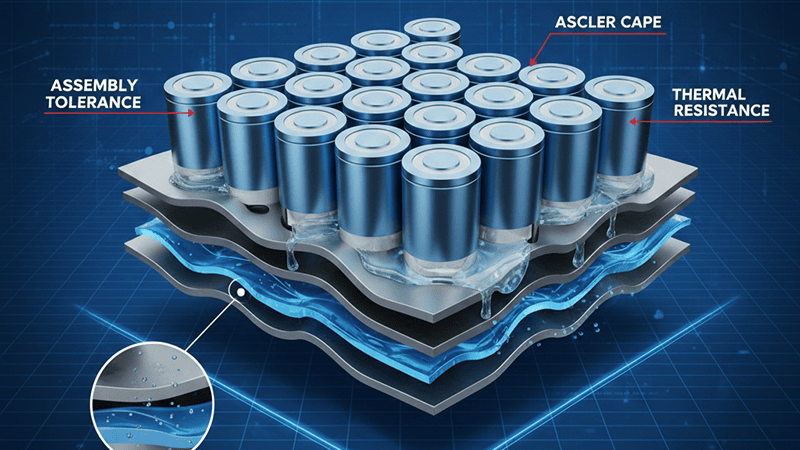
Assembly Tolerances in Battery Modules
All battery modules are constructed with tolerances. A tolerance refers to a limited degree of variation that is allowed when making a part of a product. One of them can be a fraction of a millimeter higher, another a fraction of a millimeter broader, another half an inch more lumpish at the bottom. This, in itself, makes these variations seem trivial. But in a pack of hundreds of cells that are stacked.
When that happens, the cooling plate can no longer sit evenly across all the cells. Some cells make full contact, others make partial contact, and a few barely touch the plate at all. The effect is that pressure is not distributed uniformly across the surface, increasing thermal resistance and creating areas where heat cannot be dissipated effectively. Prismatic cells often highlight this problem because their rigid shape magnifies tiny variances. It is a challenge with pouch cells as well, as they slide more readily within the frame.
This is where high thermal conductivity materials make a difference. They help move heat away even when mechanical contact isn’t perfect, but they cannot work effectively if the gaps grow too large.
Surface Roughness and Microscopic Unevenness
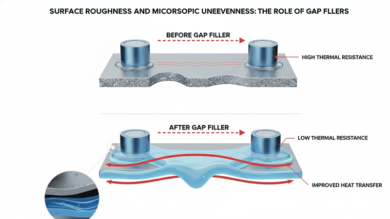
A surface may appear to be smooth, but it is not flat. Metals under the microscope possess peaks and valleys, which decrease the actual contact area between the battery cell and the cooling plate. Two surfaces may touch, but only at a fraction of their apparent surface area.
This unevenness at a microscopic scale increases thermal resistance. Heat has fewer paths to travel, so the cells begin holding more energy inside, especially during heavy loads. It is also one of the most widespread reasons why engineers resort to inorganic gap fillers that are thermally conductive. These materials are thermally conductive, soft enough to flow into tiny surface imperfections, and strong enough to improve the connection between the cells and the cooling plate. When applied correctly, they minimize the space between the cooling plate and battery cell and enhance efficient heat transfer without necessitating significant redesigns.
Cell Swelling and Mechanical Stress Changes
A perfectly assembled pack will not remain the same over time. Battery cells swell as they age and during charge and discharge cycles. This swelling has the capability of increasing or decreasing contact pressure at various points within the module. A cell that starts with good contact may slowly drift out of contact with the cooling plate.
Such little movements produce inconsistent pressure within the system. Components can be deformed by areas of excessive pressure. Areas with too little pressure form new gaps that trap heat. Both issues weaken the overall thermal management performance of the pack.
This is the reason why a lot of engineers use compressible materials, which are expected to be stable in the long term. These materials assist in keeping pressure on contact even when the cell is in the process of expansion or contraction, prolonging the life and performance of the module.
How Gaps Increase Thermal Resistance and Reduce Cooling Efficiency
Gaps between a battery cell and its cooling plate create a cascade of thermal issues that undermine the entire cooling system. When heat cannot flow freely into the cooling plate, it becomes harder to control temperatures, and the battery pack becomes ineffective. To simplify, here are the main reasons those gaps are problematic.
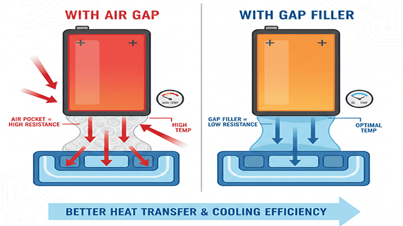
Air is a Poor Thermal Conductor
The thermal conductivity of air is very low, implying that it does not conduct heat but rather blocks it. That is why even a thin air-filled space slows the cooling process.
In comparison, the conductivity of thermal interface materials and gap fillers is much superior. They seal off the air bubbles and enable the movement of heat out of the cell into the cooling plate with ease.
A simple way to picture this is to think of placing something warm on a hard table versus placing it on a soft cushion. On the table, the warmth moves quickly; on the cushion, it stays trapped. This effect also occurs internally in the pack, where an air space exists between the surface and the cooler cell.
Contact Thermal Resistance (Rᴛᴄ) Explained Clearly
When the surface of the cell does not make firm contact with the cooling plate, contact thermal resistance rises. More resistance means worse heat transfer, and the cooling system must be more effective to remove heat.
As the gap increases, heat leaves the cell at a slower rate. This causes unforeseen temperature variations within the battery pack, making thermal control difficult and performance management more challenging. These minor differences accumulate with time and establish bigger imbalances throughout the pack.
The Critical Impact on Safety and Battery Life
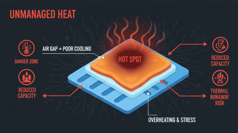
Poor heat transfer affects much more than efficiency. The cells heat up quickly during fast charging, and any distance between them will reduce the effectiveness of a cooling plate. The outcome is an increased temperature and increased stress on the cell structure.
If these hot spots continue, the battery may age faster, lose capacity sooner, or face higher risks in extreme scenarios. Unmanaged gaps increase the risk of conditions that contribute to thermal runaway.
The application of thermal interface material, reliable gap fillers, and well-designed liquid cooling systems can be used to ensure healthy operating temperatures and contribute to the long-term energy storage functionality.
4 Common Engineering Scenarios That Create Gaps Between Battery Cells and Cooling Plates
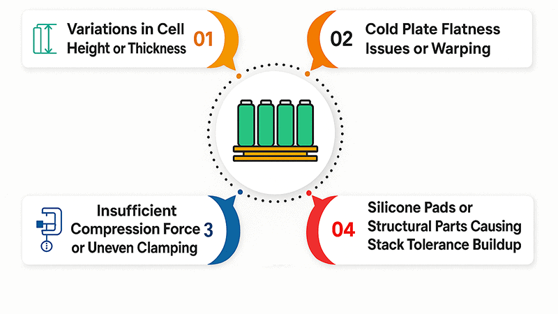
Gaps rarely come from one big mistake. They are a product of mundane engineering realities within a battery module, where even minor variations cumulate and disrupt contact between cells and the cooling surface.
The following scenarios are the most common reasons gaps appear and limit a module’s ability to transfer heat efficiently.
- Variations in Cell Height or Thickness (Manufacturing Variability)
Every supplier works within tolerance ranges, and those ranges affect electric vehicles more than most engineers expect. When cells arrive with slight differences in height or thickness, the pack no longer compresses evenly. Even a fraction of a millimeter breaks consistent contact, lowering effective thermal conductivity and slowing heat movement into the cooling plate.
Across hundreds of cells, these variations stack up. Some cells end up firmly pressed into the cooling structure, while others rest just lightly against it. This difference causes uneven temperatures inside the battery systems, which affects performance and increases energy consumption as cooling components work harder to compensate.
- Cold Plate Flatness Issues or Warping
Cold plates, especially aluminum ones, rarely remain perfectly flat once integrated into the module. Machining tolerances, fastener locations, and temperature cycling can introduce subtle warping.
When a plate bends even slightly, zones of poor contact appear, blocking smooth heat transfer and reducing the efficiency of liquid cooling systems or passive cooling systems. This effect becomes more visible over time as the plate expands and contracts during charging and discharging cycles.
- Insufficient Compression Force or Uneven Clamping
The cooling approach in electric vehicles depends heavily on consistent compression. When clamping pressure varies across the module, some areas form strong contact while others lift away, creating pockets that slow cooling.
Uneven compression typically comes from bracket designs, uneven fastener torque, or natural tolerance buildup during assembly. These inconsistencies interrupt heat flow and place additional stress on the cooling loop or active cooling system trying to stabilize temperatures.
- Silicone Pads or Structural Parts Causing Stack Tolerance Buildup
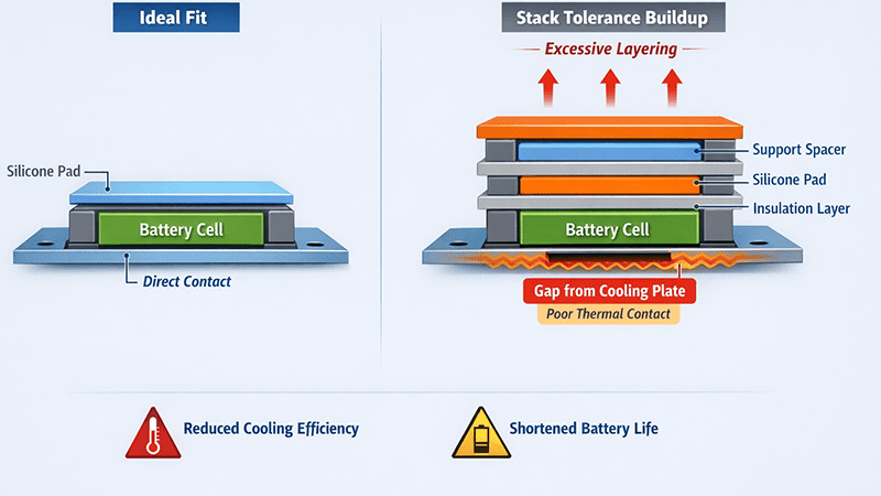
Module designs often rely on silicone pads, insulation layers, or structural supports. While necessary, each added layer increases the total stack tolerance. As these tolerances accumulate, cells no longer sit flush with the cooling plate.
Even materials designed to help cooling can work against the system when the stack height grows beyond the intended range. This reduces effective thermal conductivity, limits cooling efficiency, and contributes to premature performance loss or a shorter battery lifespan.
How Engineers Can Identify and Measure Hidden Micro-Gaps

Micro-gaps can be overlooked at the assembly stage, but they define all the aspects of the battery pack design, efficiency, and overall performance in the long run. The following methods help engineers confirm contact quality, measure uneven surfaces, and understand how each cell interacts with the cold plate:
Feelers, Laser Scanners, and Profilometry
Simple tools such as feeler gauges are still used to test the quality of contacts, particularly in checking edges and corners, and places where a lithium ion cell will not fit. For deeper insight, laser scanners and surface profilometry can give fine details on the levelness, change of height, and micro-textures of components.
These measurements reveal where a surface creates a natural heat sink connection and where small gaps interrupt convective heat transfer. Even minor deviations in electric vehicles restrict the temperature control, and they force the cooling system to operate at its maximum, which requires more electrical energy to bring the pack to the desired temperature in hot weather.
Pressure Mapping Films (Fuji Prescale Method)
Among the most efficient and easiest methods of ensuring actual contact on the module is the use of pressure mapping films. The film appears darker in the areas of high pressure and lighter in the areas of weak contact between the cell and the cold plate.
This visual pattern forms a full story of an engineer. It demonstrates areas of compression that help minimize thermal resistance and areas of low pressure that form pockets that slow the rate of heat transfer between the source of heat and the cooling plate.
In EV pack development, pressure mapping is necessary to confirm the efficiency of thermal pads or interface material under load and to confirm that all portions of the surface are provided with the required support to increase conductivity.
Predictive Modeling Using FEA and Digital Twins
The contemporary pack design is highly reliant on simulation. The Finite Element Analysis (FEA) and digital twins aid engineers in making predictions regarding the deformation of the materials, cell aging, and the movement of heat across a battery pack. These tools simulate convective heat transfer, compression patterns, and thermal distribution to identify potential micro-gaps before the prototype stage.
Through the knowledge of swelling, vibration, and cycling to change the structure of time, engineers can make early changes in design, enhance battery pack design, and enhance long-term durability in electric cars.
Why Thermal Interface Materials (TIMs) Are Important for Eliminating Gaps

In recent times, engineers have shifted to relying on Thermal Interface Materials (TIMs). These TIMs are designed to fit into the uneven surfaces, enhance thermal contact, and hold the cooling structure in regular operation and high temperatures of operation.
The following points explain how TIMs help EV battery packs stay stable and efficient:
Filling Invisible Micro-Gaps to Improve Heat Transfer
Even when surfaces look flat, they still contain microscopic peaks and valleys that trap air. Because air has poor thermal conductivity, these pockets slow heat flow between the cell and the cooling plate. Thermally conductive gap fillers address this by flowing into the gaps and creating a continuous path for heat to move through the cooling structure.
This ensures good thermal conductivity across the entire interface and supports both passive and active cooling strategies used by automotive manufacturers.
Maintaining Cell Temperature Consistency (≤3–5°C)
In EV battery packs, the goal is not just keeping temperatures low; it is keeping them even. A difference of more than 3–5°C across cells can affect aging rates, charging behavior, and performance. TIMs assist in preventing those swings by forming consistent contact pressure and constant route to heat.
Having higher heat dissipation cells acts in a more regulated environment that prevents the battery from undergoing stress when charging fast, operating on a heavy load, or on long journeys with high operating temperatures.
Reducing Contact Thermal Resistance Under Variable Load
Vibration and expansion cycles alter the clamping of the components during driving. In the absence of a flexible material on the interface, these changes augment thermal resistance.
Compressible TIMs like pads, gels, or phase change materials maintain consistent thermal contact by adjusting to the changing shape of the assembly. This suppresses hotspots and makes the temperature behavior predictable during normal operation.
Which TIM Types Work Best for Gap Issues
Different gap challenges call for different TIM types. Thermal pads provide a stable, solid layer for areas with consistent compression. Thermally conductive gap fillers work well for uneven or shifting surfaces because they flow into all available spaces. Phase change materials soften at operating temperature and form a seamless thermal path.
Each option supports good thermal conductivity, reliable heat dissipation, and a low cost way to strengthen thermal performance in pack designs.
External Resources and Technical References
However, as engineers refine the battery module design, research continues to point to the same conclusion: contact quality can narrow the gap between theory and practical performance to a fine line. As recent research on the performance of active cooling systems has shown, a slight improvement in surface matching can lead to a noticeable change in heat transfer across a pack. These results agree with those of most teams in testing, particularly when enhancing thermal contact under actual operating pressure.
Other reports from battery safety groups highlight another pattern. Gaps remain unaddressed, and temperature disparities will initially increase gradually, but when the cells are strained, they will increase rapidly. Researchers refer to this as an avoidable failure curve, and it can be prevented using the appropriate materials and compression. It also explains why additional EV programs are reconsidering their initial module designs: evidence shows that intelligent material selection can enhance cooling performance while remaining highly cost-effective.
Collectively, such publications provide engineers with something worthwhile. They verify the daily struggles observed on the shop floor and provide factual advice on how to rectify them. And as more vehicles move toward greater power, these lessons will continue to influence how teams build, develop, and test their next-generation cooling systems.
Conclusion
Strong thermal performance begins early in the design phase. When engineers take time to study how each cell meets the cooling plate, they give their battery systems a stronger foundation that holds up under stress. Small air gaps may seem harmless at first, but they quietly interrupt heat flow, weaken electrical insulation, and create temperature swings that show up later during fast charging or high-load operation. That is why the next steps matter so much.
Running reliability tests, checking pressure distribution, and choosing materials that maintain contact at high speed and under real conditions can make the difference between a stable system and one that fails too soon, even when working with low cost constraints.
This naturally leads to a deeper question every engineer faces as these designs evolve: how do you choose the right material that can hold its shape, stay consistent under pressure, and close those hidden gaps? That is the focus of our next article, where we will discuss how to choose the right thermal material for filling micro-gaps
CTA

If your team is working to improve thermal performance in EV battery systems, JIUJU can support you with engineering guidance grounded in real testing. We are interested in the material’s ability to maintain stable contact, provide high reliability, and limit its long-term environmental impact.
The other technical resources we offer involve teams helping make comparisons of materials with confidence. And if you need clarity when designing your next step, our engineers will be happy to share their experience and guide you through feasible alternatives.
