
Introduction
Choosing the wrong thermal pad for a PCB can crack an IGBT, void a product warranty, or stall an entire assembly line — and most of these failures trace back to decisions made in the first ten minutes of thermal design. This guide walks hardware engineers, PCB layout designers, and thermal engineers through the three decisions that matter most: how to select the right thermal pad, how to apply it correctly, and how to troubleshoot common heat dissipation failures.
Unlike generic datasheet summaries, the recommendations below come from real field experience across motor control systems (including a documented IGBT cracking incident), consumer electronics, and gaming console thermal projects — covering the practical traps that spec sheets rarely warn you about. Let’s start with what a thermal pad actually does inside a PCB assembly.
What Is a Thermal Pad and Why It Matters for PCBs
A thermal pad is a pre-formed, soft, electrically insulating sheet — typically silicone-based and filled with ceramic or boron nitride particles — placed between a heat-generating component and a heat sink or metal chassis to conduct heat away while maintaining electrical isolation.
In a real PCB assembly, a thermal pad does four jobs at once:
- Heat transfer — moves thermal energy from hot components (IGBTs, MOSFETs, GPUs) into the heat sink or enclosure
- Electrical insulation — prevents short circuits between exposed pads, leads, and heat sink surfaces
- Gap filling — fills the uneven air gap between component tops and heat sink baseplates (typically 0.3–3.0 mm in real-world designs)
- Vibration damping — absorbs mechanical shock in automotive, motor control, and portable devices
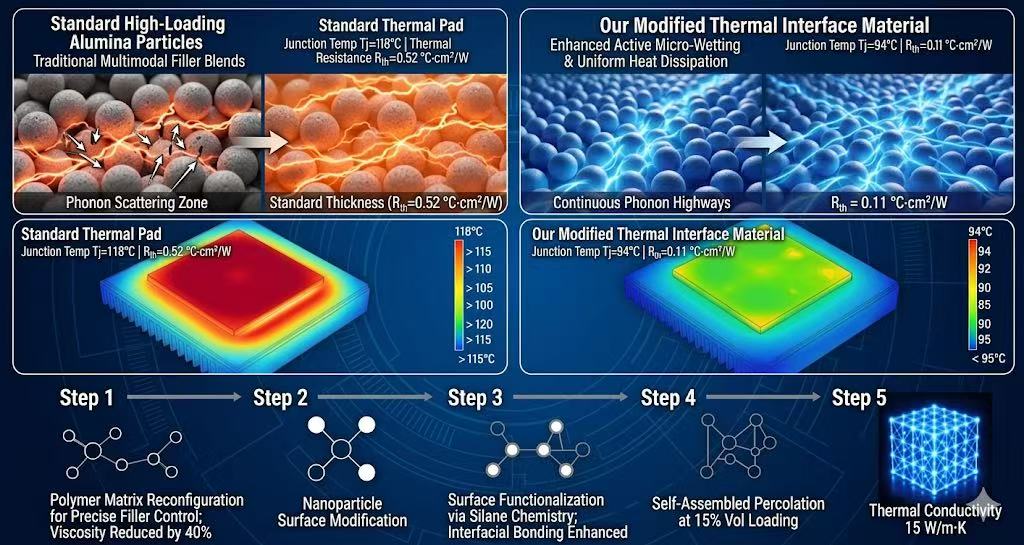
The real engineering value lies in reducing thermal resistance (Rθ) at the interface. Air is a poor thermal conductor (~0.025 W/m·K), so even a 0.1 mm air gap can trap enough heat to push junction temperatures 15–20 °C higher. A properly selected thermal pad (1.5–15 W/m·K) replaces that air with a continuous conductive path, keeping the junction safely within its operating limit.
Thermal pads become mission-critical in three scenarios we encounter again and again:
- High-power ICs — voltage regulators, PMICs, and driver ICs dissipating more than 2 W
- Power semiconductors — IGBTs and SiC MOSFETs in motor control inverters, where junction temperatures above 150 °C dramatically shorten lifespan
- High-density compute — GPUs, CPUs, and SoCs in gaming consoles, where sustained thermal throttling directly hurts the user experience
Skip the thermal pad, undersize it, or pick the wrong hardness — and you’ll run straight into the kind of field failure documented in Section 6.
Common Thermal Pad Types and Conductivity Targets

Not all thermal pads are created equal. Choosing the wrong type — or chasing a higher W/m·K number than your design actually needs — is one of the most common (and most expensive) mistakes we see in thermal reviews. This section breaks down the three pad families used in real PCB projects, and matches each to a realistic conductivity target.
Three Thermal Pad Types You’ll Actually Use
Silicone-based pads are the workhorse of PCB thermal design. They’re soft, conformable, and available across a wide conductivity range (1.0–15 W/m·K), which makes them the default choice for 80% of applications — from LED drivers to motor control modules. Trade-off: silicone outgassing can be a concern in optical or sealed enclosures.
Graphite pads are anisotropic, meaning they conduct heat far better in-plane (up to 1500 W/m·K) than through-plane (5–20 W/m·K). They’re ultra-thin (0.025–0.2 mm) and ideal for tight gaps in smartphones, SSDs, and slim laptops — but they’re electrically conductive, so insulation must be handled separately.
Phase-change pads stay solid at room temperature and soften (or partially liquefy) above 45–60 °C, wetting the interface like grease without the mess. They deliver the lowest thermal resistance of the three and are the go-to choice for high-performance CPUs, GPUs, and server processors where every 0.1 °C·in²/W counts.
Conductivity Selection Guide (Don’t Overspec)
A higher W/m·K number always costs more — and rarely delivers proportional performance gains once you exceed the design budget. Use this field-tested guide:
| Power Class | Typical Applications | Recommended Conductivity |
|---|---|---|
| Low-power | Consumer electronics, LED lighting, IoT devices | 1.5–3 W/m·K |
| Mid-power | Routers, SSDs, set-top boxes, small inverters | 3–6 W/m·K |
| High-power | IGBT modules, GPUs, power inverters, EV chargers | 6–15 W/m·K |
Rule of thumb from the bench: if your thermal simulation shows junction temperature margin above 15 °C with a 3 W/m·K pad, don’t pay 3× more for a 10 W/m·K version. Spend that budget on better airflow or a larger heat sink instead.
Choosing the Right Thickness — The 20%–40% Compression Rule
If there’s one chapter in this guide you should bookmark, it’s this one. Thickness selection is where most thermal pad failures actually originate — not in the lab, but on the assembly line and in the field. After 15+ years debugging thermal issues across motor control, power electronics, and consumer hardware, I can tell you with confidence: get the compression ratio wrong, and nothing else in your thermal stack matters.
Measuring the Real Gap (Tolerance Stack-Up Counts)
The first mistake engineers make is measuring the nominal gap from the 3D model and calling it done. In reality, you need to account for:
- Component height tolerance (typically ±0.1–0.3 mm for power modules)
- PCB warpage (±0.5% of diagonal length per IPC-A-610)
- Heat sink machining tolerance (±0.05–0.15 mm)
- Mounting screw torque variation (changes the gap by 0.1–0.2 mm)
Stack these up, and a “1.0 mm” nominal gap can swing anywhere from 0.7 mm to 1.4 mm in production. Your pad thickness must accommodate the worst case on both ends.
Standard thicknesses to choose from: 0.5 / 1.0 / 1.5 / 2.0 / 3.0 mm (custom thicknesses available, but lead times double).
Engineer’s Field Note — Two Failure Modes I See Every Month
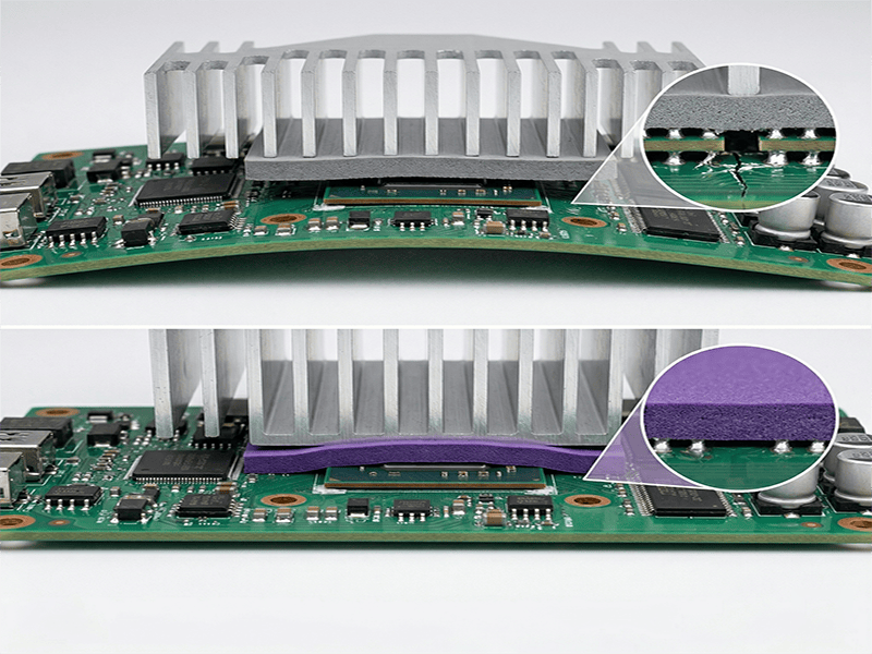
Failure Mode 1: Too thin → incomplete contact The pad can’t fill the gap, micro air pockets form at the interface, and thermal resistance jumps 2–3×. The component runs hot, throttles, and eventually fails — but the root cause looks like “bad chip” in the failure report.
Failure Mode 2: Too thick → excessive assembly pressure The pad resists compression, the mounting screws transfer that force directly into the component package, and you get cracked die, broken solder joints, or delaminated substrates. This one is brutal because the damage often doesn’t show up until thermal cycling in the field.
Real Case — IGBT Cracking at a Motor Control Client
A client building 7.5 kW motor drives came to us with a 4% field failure rate after 6 months. The symptom: IGBT modules cracking along the ceramic substrate.
Root cause we found: their thermal design team had specified a 2.0 mm pad for a measured 1.3 mm gap — a forced 35% compression, but on a pad with Shore 00 hardness of 75 (far too stiff). The actual mounting pressure exceeded the IGBT’s 40 N/cm² tolerance and cracked the DBC substrate during torque-down.
Our fix: switched to a 1.8 mm pad with Shore 00 hardness 50, targeting 30% compression. Failure rate dropped to zero in the next 12-month field data window.
Practical Formula — How to Calculate Pad Thickness
Pad Thickness ≈ Measured Gap ÷ (1 − Target Compression Ratio)Example: 1.0 mm gap × 30% target compression → 1.0 ÷ (1 − 0.30) = 1.43 mm → Select the closest standard thickness: 1.5 mm
Always design for 20%–40% compression:
- Below 20%: contact is unreliable, air gaps form
- Above 40%: stress on the component rises sharply, and the pad starts to “compression set” (permanent deformation), losing performance over time
Material Tip — Why 30% Compression Often Becomes 10% in Real Life
Here’s the trap that catches even experienced teams: datasheets quote compression ratios under lab conditions (slow, controlled press, soft Shore 00 ≤ 40 samples). On a real assembly line with fast torque-down and harder pads, you often achieve only 10–15% — meaning your stack-up height grows, the enclosure won’t close flat, and screws have to fight the pad instead of clamping the heat sink.
What we’ve done to fix this in our own pad line:
- Maintained Shore 00 hardness in the 40–60 range across the full 1.2–15 W/m·K conductivity range
- Verified compression behavior under real assembly conditions (not just ASTM D575 lab tests)
- This means the 30% compression you spec is the 30% you actually get
Bottom line — before you order any thermal pad, check three lines on the datasheet:
- ✅ Thermal conductivity (W/m·K)
- ✅ Shore 00 hardness (this is the one most engineers skip)
- ✅ Compression set (%) at 70 °C / 1000 hrs
If the datasheet doesn’t list Shore 00 hardness — walk away. You’re buying a number, not a solution.
Application Steps and Handling
- remove protective film (both sides if dual-film)
- clean mating surfaces with isopropyl alcohol
- align pad to component before placement
- apply uniform pressure during seating
- inspect for air bubbles or misalignment after installation
Thermal Pad vs Thermal Paste vs Thermal Tape

One of the most common questions we get: “Why not just use thermal paste — it has lower thermal resistance, right?“ The honest answer: it depends on your gap, assembly process, and production volume.
Head-to-Head Comparison
| Property | Thermal Pad | Thermal Paste | Thermal Tape |
|---|---|---|---|
| Gap filling | Excellent (0.5–5 mm) | Poor (<0.1 mm) | Limited (<0.25 mm) |
| Reusability | ✅ Reusable | ❌ Single use | ❌ Single use |
| Application | Easy, clean | Messy | Peel-and-stick |
| Adhesion | Light tack | None | Strong |
| Mass production | ✅ Die-cut, automated | ❌ Hard to dispense | ✅ Pre-cut |
| Best for | Large gaps, high volume | CPU/GPU, lowest Rθ | Lightweight heat sinks |
When to Pick Each One
- Thermal pad — gap >0.3 mm, high-volume production, field-serviceable designs
- Thermal paste — gap <0.1 mm, CPU/GPU with clamping pressure, lowest Rθ needed
- Thermal tape — lightweight components, no screws available, adhesion is the mounting
Field Reality Check
In our experience, 80% of mid-to-high-power PCB designs end up using thermal pads — not because they win on paper, but because they survive real-world tolerance stack-up and mass production. Paste wins benchmarks; pads win product lifecycles.
Integration with PCB Design
A thermal pad can only perform as well as the PCB it sits on. The best material in the world won’t save a board where heat has nowhere to go. Here are the four layout rules we enforce in every design review:
Place Thermal Vias Directly Under Hot Components
Add a dense via array (typically 0.3 mm drill, 1.0 mm pitch) directly beneath power devices — MOSFETs, IGBTs, PMICs. Vias pull heat from the top copper to the bottom layer, where the thermal pad and heat sink take over. Without vias, even a 15 W/m·K pad underperforms.
Group Similar Heat Sources Together
Cluster components with similar power dissipation into thermal zones. This lets you use a single die-cut pad instead of multiple small pieces — reducing BOM complexity, assembly time, and the risk of misplacement on the line.
Couple Pads to Chassis When No Heat Sink Exists
In compact designs (IoT modules, automotive ECUs), there’s often no room for a dedicated heat sink. Use the metal enclosure as the heat spreader — a thermal pad between PCB and chassis turns the entire housing into a passive cooler.
Document Everything on the Assembly Drawing
Pad thickness, exact placement, orientation, part number, and supplier — all of it belongs on the PCB assembly drawing. We’ve seen multiple field failures traced to assembly line workers swapping a 1.5 mm pad for a 2.0 mm “because we ran out” — undocumented changes that nobody caught until thermal failures hit the field.
Common Mistakes and Troubleshooting
After supporting hundreds of thermal designs, we see the same five mistakes repeat. Avoid these, and you’ll skip 90% of field failures.
The Five Mistakes That Kill Thermal Performance
❌ Pads too thin → air gaps Under-spec’d thickness leaves micro-gaps that air fills. As shown in the IGBT case earlier, a 0.5 mm shortfall raised junction temperature by 18 °C.
❌ Excessive compression → component damage If the enclosure needs unusual force to close, stop and re-measure. Forcing it cracks solder joints, lifts BGAs, and over-compresses pads past their elastic limit.
❌ Ignoring Shore 00 hardness Many “high W/m·K” pads on the market (>6 W/m·K) are too hard to compress properly. A 12 W/m·K pad that won’t conform performs worse than a 3 W/m·K pad that does. Always request the Shore 00 datasheet value before sampling.
❌ Reusing pads after disassembly Surface contamination — dust, fingerprints, oxidation — raises thermal resistance by 20–40%. If you must reopen a unit for rework, replace the pad.
❌ Skipping post-assembly inspection Air gaps and uneven contact are invisible from the outside. They only show up as thermal failures three months later in the field.
The One Habit That Prevents Most Failures
✅ Always inspect for air gaps and uniform contact after assembly. A 30-second visual check on the first article saves months of RMA pain.
Conclusion and Next Steps
Choosing the right thermal pad isn’t guesswork — it’s a repeatable engineering process. Get the inputs right, and the heat takes care of itself.
Key Takeaways
- Measure the gap between component and heat sink (use feeler gauges or 3D CAD)
- Calculate thickness allowing for 20%–40% compression
- Verify Shore 00 hardness — softer pads beat harder ones at real-world conformity
- Validate with samples before locking in for mass production
Skip any step, and you’re rolling the dice on field reliability.
Your Next Move

Don’t wait until prototype testing reveals a thermal problem. Take action this week:
Measure your component-to-heat sink gap today Request a datasheet with full thermal and mechanical specs — including Shore 00 Order die-cut samples matching your exact PCB layout for thermal validation
A 2-week sample cycle now prevents a 6-month redesign later.

