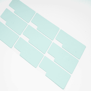

Thermal conductivity tells you how readily heat moves through a material. Thermal pad thickness tells you how far heat must travel through it. For the same area and material, a thinner pad has lower bulk thermal resistance—but only if it still fills the gap and maintains contact.
That last condition is the trap. A thin high thermal conductivity pad with incomplete contact can lose to a thicker, softer pad that removes the air gap.
The first-order relationship
For one-dimensional conduction through a uniform layer:
Rbulk ≈ t / (k × A)
where:
Rbulkis bulk thermal resistancetis compressed thicknesskis apparent thermal conductivityAis heat-flow area
Double the thickness with everything else constant, and the bulk portion of resistance roughly doubles. Double thermal conductivity, and it roughly halves.
Real interfaces add contact resistance at both surfaces. Pressure, roughness, flatness, filler distribution, and conformity change the result.

Why W/m·K does not predict the installed temperature
ASTM D5470 measures steady-state thermal impedance of thermally conductive electrical insulation materials. The standard notes that practical applications do not reproduce its idealized, parallel heat-flow conditions. It also describes using multiple specimen thicknesses to separate apparent thermal conductivity from contact resistance.
When you compare two pads, ask:
- At what thickness was impedance reported?
- What pressure or load was applied?
- What was the average test temperature?
- Was the sample reinforced or adhesive-backed?
- Does the value include both interfaces?
- Is thermal conductivity measured or derived from a family model?
A thermal conductivity number without these conditions is a material-screening input, not a device-temperature guarantee.
A simple comparison example
Consider the same 400 mm² contact area:
- Pad A: 1.0 mm compressed thickness, 5 W/m·K
- Pad B: 2.0 mm compressed thickness, 10 W/m·K
Using only the bulk equation, both have the same bulk resistance because Pad B doubles both thickness and thermal conductivity. But the installed results can differ because their contact resistance and required compression pressure may not match.
If Pad A makes complete contact at low force and Pad B is too hard to conform, Pad A can perform better. If Pad A cannot bridge the real gap, its theoretical advantage is irrelevant.
Choose thickness first—or thermal conductivity first?
Neither in isolation. Use this sequence:
- Define the minimum and maximum gap.
- Define the component and assembly force limits.
- Shortlist materials that can conform across that range.
- Compare thermal impedance at the required thickness and pressure.
- Confirm electrical, environmental, and contamination requirements.
- Test the actual assembly.
The thermal pad thickness selection guide provides the geometry and tolerance calculations.
Before comparing two thermal conductivity values, confirm that both candidates perform the same interface job. A compressible pad, flowable gap filler, paste, and phase-change material can have very different useful bond-line ranges and process controls. Their W/m·K values are not a normalized ranking.
For a fair shortlist, compare installed thermal impedance at the required bond-line thickness, pressure, and temperature. Then add the mechanical and reliability constraints: conformity, total force, electrical isolation, material movement, rework, and aging. A candidate should not advance merely because it has the largest thermal conductivity number in a mixed-material table.
When a higher thermal conductivity pad may not help
It is harder at the required grade
Higher filler loading can increase thermal conductivity while also changing hardness and compression response. If the pad needs more force than the assembly can supply, contact may worsen.
It is available only in a thicker construction
The longer path can offset part of the thermal conductivity gain. Compare impedance, not just W/m·K.
The heat path is limited elsewhere
The component package, heat spreader, cold plate, convection path, or coolant loop may dominate total resistance. Improving the pad alone then produces a small temperature change.
The contact area is smaller than expected
Package curvature, board bow, surface roughness, or poor placement can reduce effective area.
Why the filler system changes more than thermal conductivity
A thermal pad is a polymer matrix loaded with thermally conductive particles. Moving to a higher thermal conductivity target may change filler type, particle-size distribution, surface treatment and loading. Those changes can affect viscosity during mixing, calendering behavior, hardness, compression force, electrical behavior and long-term stability.
Jiuju’s documented incoming-control workflow checks filler particle-size points such as D10, D50 and D90, plus mixed viscosity and volatile content. Its development material lists candidate filler families across thermal conductivity targets, including aluminum hydroxide, alumina, aluminum nitride, boron nitride, diamond, aluminum and carbon fiber. These are formulation candidates, not a claim that every pad contains every filler.
That distinction matters for specifications. A conductive particle may improve a heat path but also change electrical risk. Do not infer dielectric insulation from thermal conductivity or from a generic family name. Request the exact grade’s volume resistance, breakdown data, compressed thickness and construction.
Jiuju also documents a dry surface-modification process in which a polymer modifier is sprayed onto dispersed inorganic powder and forms a surface coating through chemical interaction. The design intent is better particle compatibility and dispersion in the matrix. The safe engineering conclusion is that particle treatment is one formulation control; any claimed performance gain still needs a matched test report.
How to screen a candidate pad
Use a staged comparison so a high W/m·K number does not hide a mechanical mismatch:
- Confirm that the candidate covers the minimum and maximum gap.
- Compare Shore 00 hardness and the full compression-deflection curve.
- Compare thermal impedance at the intended thickness, pressure and temperature.
- Verify electrical isolation, reinforcement, adhesive and contamination requirements.
- Review lot-control data for thickness, hardness and the agreed thermal check.
- Validate the installed assembly before and after relevant aging or cycling.
Jiuju’s laboratory list includes particle-size analysis, viscometry, Shore 00 and thickness measurement, compression testing, ASTM D5470 thermal testing, high-resistance and breakdown-voltage testing, and environmental chambers. The list does not make all grades equivalent. It shows which questions can be converted into measurements when the project specification identifies the risk.

How Jiuju reports the material range
Jiuju reports thermal-pad thermal conductivity from 1.2 to 25 W/m·K, with JIUJU625X identified as the highest reported grade. Its current public thermal pad specification table lists standard models from 2.0 to 6.0 W/m·K with thickness, Shore 00 hardness, resistance, and electrical data.
For grades outside the public table, request the current TDS and test report. Confirm specimen thickness, pressure, test method, and whether the value applies to the exact production construction.
Jiuju also reports that each thermal-pad shipment can include thermal conductivity, hardness, dimensions, appearance, and agreed customer checks. Put the acceptance method and frequency in the quality agreement.
Before comparing two grades, request one row of matched data: exact construction, free and test thickness, pressure, mean temperature, thermal impedance, Shore 00, and compression stress at your design strain. That row is often more useful than a page of unmatched maximum values.
FAQ
Is a 10 W/m·K pad twice as good as a 5 W/m·K pad?
Not necessarily. It halves the ideal bulk resistance only when thickness, area, and test conditions are equal. Contact and the rest of the thermal path can dominate.
Do thicker thermal pads have lower thermal conductivity?
Thickness does not change the intrinsic thermal conductivity of a homogeneous formulation, but it increases bulk resistance. Measured apparent values can also vary with test construction and interface effects.
Should I always choose the thinnest pad?
Choose the thinnest pad that fills the maximum gap and remains within the approved compression-force window at the minimum gap.
Compare fitted performance
Thermal pad thickness and thermal conductivity pull in opposite directions only in the simple bulk equation. In the real assembly, conformity and force decide whether that equation even applies.
Measure the gap, select a mechanically compatible grade, compare impedance under relevant conditions, and validate temperature. For grade selection, review Jiuju’s thermal pad products and request pressure-specific data.