
The Silent Challenge of Industrial Heat Dissipation
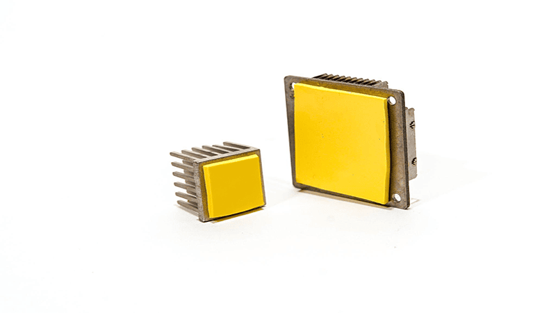
In the landscape of industrial power electronics, thermal management has evolved from a secondary consideration to a mission-critical design parameter that fundamentally determines product lifecycle and reliability. Modern motor controllers, 5G base stations, and high-frequency inverters are pushing power density boundaries to unprecedented levels, transforming thermal interface materials (TIM) from passive gap fillers into active performance enablers.
The challenge is stark: a single degree Celsius reduction in operating temperature can extend component life by 10-15%, while inadequate thermal management triggers cascading failures that cost industries millions in downtime and warranty claims. As power modules transition from kilowatt to multi-kilowatt configurations within shrinking footprints, engineers face a pivotal decision: High Conductivity Thermal Pads or Phase Change Materials (PCM)?
This debate transcends simple material selection. It represents a fundamental trade-off between mechanical flexibility and thermal performance, between assembly simplicity and heat transfer efficiency. The choice impacts not only junction temperatures but also production workflows, long-term reliability, and ultimately, the competitive positioning of industrial systems in increasingly demanding applications.
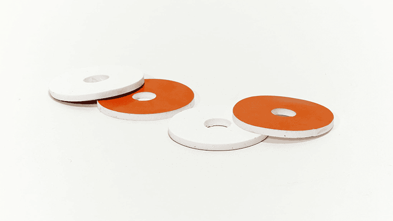
High Conductivity Thermal Pads: The Gap Filling Specialists
High-conductivity thermal pads represent the workhorses of industrial thermal management, engineered elastomer matrices that combine thermal performance with mechanical compliance. These materials are primarily formulated from silicone or non-silicone polymers infused with thermally conductive fillers such as ceramic particles, boron nitride, or aluminum oxide.
Why Engineers Love Them: The Triple Advantage
The enduring popularity of thermal pads in industrial applications stems from three core attributes that align perfectly with manufacturing realities:
1. Mechanical Stability Under Stress
Unlike greases or pastes, thermal pads maintain dimensional integrity across extreme thermal cycling (-40°C to +150°C) and mechanical vibration, critical for railway traction inverters, industrial motor drives, and outdoor telecommunications equipment. Their elastomeric nature absorbs differential thermal expansion between components without inducing mechanical stress on solder joints or substrate materials.
2. Assembly Simplicity and Repeatability
In high-volume production environments, thermal pads eliminate the variability inherent in paste application. Pre-cut to exact dimensions, they enable automated pick-and-place assembly with zero dispensing errors, no curing time, and consistent bondline thickness. This translates to 40-60% faster production cycles compared to liquid TIM alternatives.
3. Electrical Insulation as Baseline
Most industrial power modules require electrical isolation between heat-generating components and grounded heat sinks. Thermal pads inherently provide dielectric breakdown voltages exceeding 3-5 kV/mm, eliminating the need for separate insulation layers and simplifying compliance with safety standards like IEC 60664-1.
The Physical Edge: Bridging Large Mechanical Tolerances
The true engineering value of thermal pads emerges in applications with significant gap variations. Castings, extrusions, and stamped metal enclosures often exhibit surface flatness tolerances of 0.5mm to 10mm. Traditional rigid TIMs fail catastrophically in such scenarios; thermal pads compress to accommodate these variations while maintaining a continuous thermal pathway.
Modern formulations achieve thermal conductivities in the 3-10 W/m·K range, with premium grades incorporating graphite or carbon fiber reinforcement reaching up to 17 W/m·K. However, this headline specification masks a critical limitation.
Critical Limitation: Understanding the Impact of Contact Resistance
Thermal conductivity (measured in W/m·K) describes a material’s intrinsic ability to conduct heat, but it tells only half the story. In real-world applications, interface contact resistance dominates thermal performance, particularly for thicker pads (greater than 1mm). This resistance arises from microscopic air pockets trapped between the pad surface and mating components, regions where heat must conduct through air (thermal conductivity approximately 0.026 W/m·K) rather than the pad material.
Research demonstrates that a 3mm thick thermal pad with 5 W/m·K conductivity often performs worse than a 0.2mm PCM layer with identical conductivity, purely due to contact resistance effects. For applications demanding bondline thickness below 0.5mm, thermal pads become thermally and mechanically impractical, setting the stage for phase change materials.
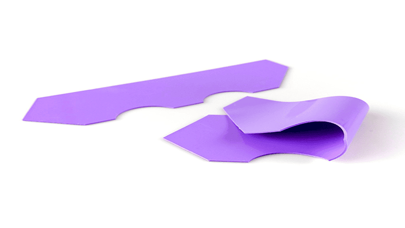
Phase Change Materials (PCM): Bridging the Performance Gap
Phase change materials represent a paradigm shift in thermal interface technology, engineered compounds that exist as handleable solids at room temperature but transition to grease-like consistency at elevated temperatures (typically 45-60°C), precisely when thermal management becomes critical.
The Science of Phase Change: From Solid Handling to Grease-Like Performance
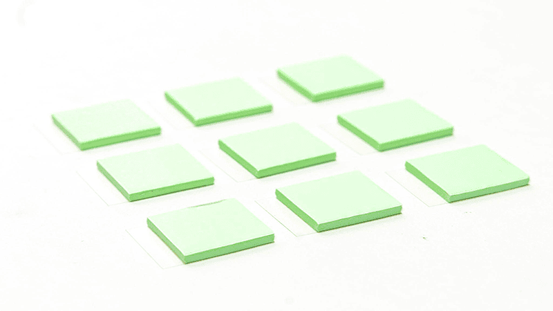
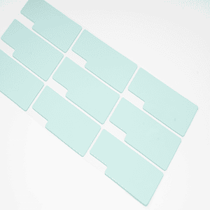
PCMs are formulated from proprietary polymer matrices combined with thermally conductive fillers and phase-change additives. At assembly, they behave as stable, non-tacky sheets that can be die-cut and positioned like traditional pads. However, once the power module reaches operational temperature, the material undergoes a controlled phase transition, reducing viscosity by orders of magnitude and flowing into microscopic surface irregularities.
This dual-state behavior solves a fundamental manufacturing challenge: achieving the ultra-low bondline thickness (BLT) of thermal grease without the mess, inconsistency, and contamination risks of liquid application.
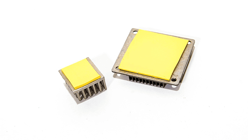
Why High-Power Modules Need PCM: Achieving Ultra-Low Bondline Thickness
In high heat flux applications, GaN power transistors, SiC MOSFETs, and concentrated photovoltaic modules, heat generation can exceed 200 W/cm². At these densities, every micron of interface thickness becomes a thermal bottleneck. Traditional thermal pads, constrained by minimum mechanical thickness requirements (typically 0.5mm or greater), introduce unacceptable thermal resistance.
PCMs excel in this regime by achieving bondline thickness as low as 25-75 microns after phase transition, comparable to expertly applied thermal grease but without application variability. The material conforms perfectly to surface topographies, creating near-metal-to-metal thermal contact. This capability is fundamental to extracting maximum performance from wide-bandgap semiconductors operating at junction temperatures approaching 175°C.
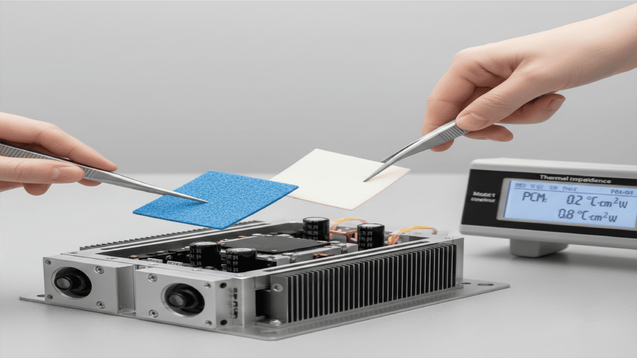
The Wetting Advantage: Eliminating Microscopic Air Pockets for 60% Better Thermal Transfer
The performance leap of PCM stems from superior surface wetting, the ability to displace entrapped air, and establish intimate contact at the molecular level. Comparative thermal impedance measurements reveal that PCM can reduce interface thermal resistance by 50-70% compared to equivalent-conductivity thermal pads, particularly in applications with moderate surface roughness (Ra 1.6-3.2 micrometers).
This advantage compounds in multi-chip modules where dozens of components share a single cold plate. Traditional pads require higher clamping pressures (often 50-100 psi) to achieve acceptable contact, risking component damage. PCMs achieve superior contact at pressures as low as 10-20 psi, enabling uniform thermal performance across large-area assemblies.
Handling and Process: Why PCM is the Modern Alternative to Messy Thermal Grease
Unlike thermal grease, which requires stenciling, dispensing equipment, and cleanroom controls, PCM integrates seamlessly into standard SMT assembly lines. The solid-state handling eliminates:
- Cross-contamination of adjacent components
- Variation in applied thickness (plus or minus 30% typical for manual grease application)
- Outgassing during reflow or high-temperature storage
- Long-term migration (pump-out) under thermal cycling
Leading manufacturers have validated PCM reliability through 3,000+ thermal cycles (-40°C to +125°C) with no measurable degradation in thermal performance, a critical requirement for automotive and industrial applications targeting 15-year operational lifetimes.
The Head-to-Head Battle: Comparison Table
Understanding that thermal conductivity alone does not determine real-world performance, the engineering decision must incorporate multiple parameters, including bondline thickness capability, mechanical compliance, and process integration.
Thermal Pads vs Phase Change Materials: Complete Performance Comparison
| Parameter | High Conductivity Thermal Pads | Phase Change Materials (PCM) | Key Insight |
|---|---|---|---|
| Thermal Conductivity | 3–17 W/m·K | 3–10 W/m·K | PCM achieves comparable or better real-world performance despite lower conductivity due to the bondline advantage |
| Bondline Thickness (BLT) | 0.5–10 mm (minimum approximately 0.5mm) | 0.025–0.3 mm (after phase change) | Ultra-thin BLT is PCM's decisive advantage in high heat flux scenarios |
| Thermal Impedance | 0.5–2.0 °C·cm²/W (thickness dependent) | 0.1–0.4 °C·cm²/W (optimized application) | PCM delivers 60–70% lower thermal resistance in controlled environments |
| Gap Filling Capability | Excellent (0.5–10mm) | Limited (0.5mm or less) | Thermal pads dominate in applications with large mechanical tolerances |
| Assembly Process | Pre-cut, pick-and-place, instant use | Pre-cut, requires heating to activate | Both support automated assembly; PCM needs a thermal activation cycle |
| Mechanical Stability | Superior under vibration and shock | Moderate; requires adequate clamping pressure | Thermal pads are preferred for high-vibration environments (rail, automotive) |
| Electrical Insulation | Standard (3–5 kV/mm) | Available in select formulations | Both can meet UL/IEC safety requirements |
| Reworkability | Fully reworkable; peel and replace | Limited; material flows cannot be cleanly removed | Thermal pads enable easier field service and prototype iterations |
Conductivity vs. Resistance: Why W/m·K Isn’t the Only Metric That Matters
The table above underscores a critical insight: thermal impedance (measured in °C·cm²/W) is the true figure of merit for TIM selection. This parameter accounts for both material conductivity and interface contact resistance, revealing why a 5 W/m·K PCM often outperforms a 10 W/m·K thermal pad in flat, high-pressure applications.
Mechanical Stability: Performance Under Vibration and Thermal Cycling
Industrial environments subject components to thousands of thermal cycles (power on/off, load transients) and continuous mechanical vibration. Thermal pads, with their elastomeric matrix, exhibit negligible performance degradation even after 10,000 cycles. PCMs, while stable, require adequate clamping pressure (minimum 10 psi) to prevent delamination, a consideration in designs with limited fastener access or large component arrays.
Selection Matrix: Which TIM is Right for Your Design?
The optimal TIM choice is application-specific, driven by thermal requirements, mechanical constraints, and production realities. The following decision matrix provides engineering guidance based on real-world deployment scenarios.
Scenario A: High Vibration and Large Gaps (Winner: Thermal Pads)
Application Examples:
Railway traction inverters, industrial servo drives, heavy construction equipment power modules, and outdoor cellular base stations.
Design Constraints:
- Gap tolerance: 1.5–5mm due to casting variations
- Vibration: 5–20G continuous, shock loads up to 50G
- Operating temperature: -40°C to +85°C ambient
- Electrical isolation required: greater than 3kV
Why Thermal Pads Excel:
The combination of large gap-filling capability and mechanical resilience makes thermal pads irreplaceable in this regime. A 3mm silicone pad with 5 W/m·K conductivity delivers thermal impedance around 0.6 °C·cm²/W, sufficient for 50-100 W/cm² heat flux when coupled with forced air or liquid cooling. The material’s ability to absorb differential thermal expansion prevents solder joint fatigue in power modules experiencing thousands of thermal cycles annually.
Recommended Specification:
Shore hardness 30-50A, reinforced fiberglass carrier, compression set less than 10% after 1,000 hours at 150°C.
Scenario B: High Heat Flux Density and Flat Surfaces (Winner: PCM)
Application Examples:
GaN RF power amplifiers (5G massive MIMO), SiC inverter modules (EV/HEV traction), high-brightness LED arrays, server CPU thermal solutions.
Design Constraints:
- Heat flux: greater than 150 W/cm²
- Surface flatness: Ra less than 1.6 micrometers (precision-machined or lapped surfaces)
- Bondline thickness tolerance: plus or minus 25 micrometers
- Junction temperature target: less than 125°C
Why PCM Dominates:
At heat flux densities exceeding 150 W/cm², every degree of temperature reduction translates directly to reliability and performance. PCM’s ability to achieve 50-75 micrometer bondline thickness delivers thermal impedance as low as 0.15 °C·cm²/W, enabling junction temperatures 15-20°C lower than equivalent thermal pads. For SiC MOSFETs, where every 10°C reduction extends lifetime by 2×, this advantage is economically decisive.
Recommended Specification:
Phase change temperature 50-55°C, thermal conductivity greater than 5 W/m·K, pre-applied adhesive backing for automated assembly.
Scenario C: High-Volume Automated Production
Application Context:
Consumer inverter air conditioners (10M+ units/year), LED driver modules, and industrial motor controllers.
Production Priorities:
- Cycle time: less than 30 seconds per assembly
- Zero-defect dispensing requirement
- Minimal work-in-process inventory
- Cleanroom-free manufacturing
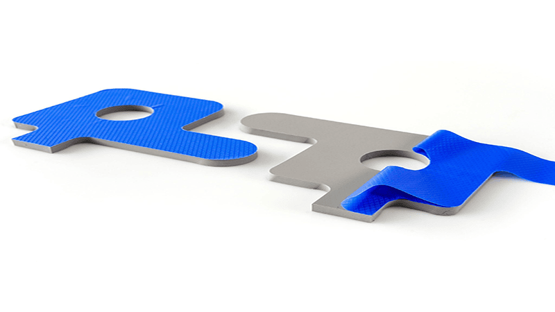
How Jiujutech Optimizes the Process:
Jiujutech’s custom die-cut solutions eliminate 90% of TIM-related production defects through precision tolerancing (plus or minus 0.1mm) and automated liner removal systems. For thermal pad applications, pre-cut parts arrive ready for robotic placement with adhesive backing pre-applied, achieving 6-sigma process capability.
For PCM applications, Jiujutech supplies phase-change pads with integrated pressure-sensitive adhesive that withstands automated component placement forces, then activates during the first power-on cycle. This approach combines PCM’s thermal performance with thermal pad’s assembly simplicity, the optimal solution for high-mix, high-volume production.
Reliability and Long-Term Performance
The true measure of TIM effectiveness emerges not in laboratory testing but across 10-15-year operational lifetimes under real-world stress. Two failure modes dominate long-term degradation: pump-out and dry-out.
Solving the Pump-out and Dry-out Crisis in Industrial Environments
Pump-out occurs when thermal cycling induces differential expansion between components, gradually extruding liquid TIM beyond the interface area. Traditional thermal greases lose 30-50% of interface coverage after 500-1,000 thermal cycles, creating hot spots and accelerating device failure.
Dry-out affects polymer-based TIMs exposed to sustained high temperatures (greater than 100°C). Volatile components evaporate, leaving behind a chalky, thermally resistive residue. This phenomenon plagued early-generation thermal pads, particularly in poorly ventilated enclosures.

Modern industrial-grade thermal pads and PCMs address these challenges through:
- Crosslinked Polymer Matrices: Preventing material flow even at 150°C continuous operation
- Non-Volatile Filler Systems: Eliminating outgassing across a 15-year service life
- Optimized Hardness Profiles: Balancing conformability with shape retention (Shore 30-50A for pads)
Independent reliability testing demonstrates that premium thermal pads and PCMs exhibit less than 5% thermal impedance increase after 3,000 thermal cycles (-40°C to +125°C), meeting automotive AEC-Q200 Grade 0 requirements.
Material Stability Over 10-15 Year Lifecycles
Long-term stability testing reveals a critical distinction: thermal pads demonstrate superior aging resistance in environments with large temperature excursions and mechanical stress, while PCMs excel in temperature-stable, high-heat-flux scenarios.
For solar inverters (25-year design life, outdoor installation, 70°C daily temperature swings), silicone thermal pads with fiberglass reinforcement remain the industry standard. Conversely, telecom equipment housed in climate-controlled shelters with continuous thermal loads increasingly adopts PCM for junction temperature optimization.
Case Study: How Choosing the Right TIM Reduced Field Failure Rates by 30%
A leading industrial motor drive manufacturer faced escalating warranty claims due to premature IGBT module failures in 75kW servo drives. Root cause analysis identified junction temperatures exceeding design limits by 12-15°C during peak load conditions.
Original Design:
2mm silicone thermal pad (4 W/m·K) with thermal impedance 0.8 °C·cm²/W
Redesign Strategy:
Transitioned to precision-machined heat sink interface (Ra 1.6 micrometers) with 75 micrometer PCM layer (6 W/m·K), achieving thermal impedance 0.25 °C·cm²/W.
Results:
- Junction temperature reduced by 18°C under rated load
- Predicted IGBT lifetime extended from 8 years to 15+ years
- Field failure rate decreased by 32% over an 18-month monitoring period
- Warranty cost savings: 1.2 million dollars annually
This case underscores that TIM selection, when integrated with holistic thermal design (heat sink optimization, airflow management), delivers measurable business impact beyond component-level performance metrics.
Conclusion: Engineering the Future of Industrial Cooling
The thermal pad versus PCM debate resists simplistic answers; both materials serve critical, non-overlapping roles in industrial thermal management. The decision framework must prioritize application-specific requirements over generic material properties.
Summarizing the Trade-offs
Choose Thermal Pads When:
- Gap tolerances exceed 0.5mm
- High mechanical vibration or shock loads are present
- Electrical insulation is mandatory
- Field serviceability and rework are required
- Production environments lack temperature-controlled assembly
Choose PCM When:
- Heat flux density exceeds 150 W/cm²
- Surface flatness enables less than 0.3mm bondline thickness
- Junction temperature reduction directly impacts product competitiveness
- Automated assembly with thermal activation is feasible
- Application operates in temperature-stable environments
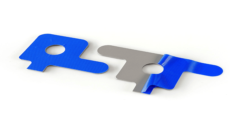
Why Jiujutech’s Custom-Cut Solutions Are the Industry Standard
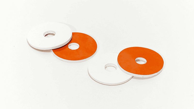
Jiujutech has established market leadership by recognizing that TIM performance is inseparable from manufacturing precision. Custom die-cutting services with plus or minus 0.05mm tolerances, application-specific material formulation, and integrated adhesive systems transform commodity materials into engineered thermal solutions.
Whether optimizing a thermal pad for 5mm gap variation in railway applications or formulating a PCM with 52°C phase change temperature for 5G power amplifiers, Jiujutech’s engineering-first approach ensures that material selection aligns with both thermal requirements and production realities.
Final Verdict: Choosing for Performance vs. Choosing for Process
The most sophisticated thermal analysis loses value if the selected TIM cannot be reliably manufactured at scale. Conversely, the most assembly-friendly material fails if it cannot maintain junction temperatures within device ratings.
Excellence in industrial thermal management demands simultaneous optimization of thermal performance, mechanical reliability, and manufacturing feasibility, a systems-level challenge where material selection is merely the foundation. As power electronics continue their relentless march toward higher efficiency and greater power density, the TIM industry must evolve beyond commodity suppliers to become strategic partners in thermal system design.
The future belongs to those who recognize that thermal interface materials are not passive gap fillers but active enablers of next-generation industrial systems, and that choosing the right material, at the right thickness, with the right application process, is an engineering discipline deserving the same rigor applied to circuit design and mechanical engineering.
Take the Next Step in Your Thermal Design
Need help selecting the right TIM for your specific application?
Whether you’re designing high-power industrial modules, automotive electronics, or consumer devices, choosing the optimal thermal interface material can make the difference between field success and warranty claims.
Get Expert Support:
Download Our Free Resources:
Request Custom Testing:
- Contact our thermal engineers for a free design review
- Receive prototype samples tailored to your exact specifications
- Get thermal impedance testing reports within 5 business days
Explore Our Product Line:
- Browse High-Performance Thermal Pads (1-17 W/m·K)
- Discover Phase Change Materials for Ultra-Low BLT
- Review Custom Die-Cutting Solutions
�� Talk to a Thermal Engineer Today:
Email: tiger.lei@jiujutech.com
Phone: +86 136 5626 9868
Response Time: Within 12 hours
Frequently Asked Questions (FAQ)
When should I choose thermal pads over phase change materials?
Choose thermal pads when your application has gap tolerances exceeding 0.5mm, requires electrical insulation, operates in high-vibration environments, or demands field serviceability. Thermal pads excel in applications like railway inverters, outdoor telecom equipment, and industrial motor drives where mechanical stability is critical.
What thermal conductivity do I need for my application?
For consumer electronics and low-power devices, 1-5 W/m·K thermal pads are typically sufficient. High-power modules like SiC inverters or GaN amplifiers benefit from 6-15 W/m·K materials or phase change materials. However, thermal impedance (not just conductivity) determines real-world performance; consult Jiujutech’s engineering team for application-specific recommendations.
How do I prevent pump-out and dry-out failures in my thermal design?
Select materials with crosslinked polymer matrices and non-volatile filler systems. Modern industrial-grade thermal pads and PCMs from Jiujutech are engineered to maintain less than 5% thermal impedance increase after 3,000 thermal cycles (-40°C to +125°C), meeting automotive AEC-Q200 Grade 0 requirements.
Can phase change materials be used in automated production?
Yes. Unlike thermal grease, PCMs arrive as solid, pre-cut pads that integrate seamlessly into pick-and-place assembly lines. The material activates during the first power-on cycle, achieving ultra-low bondline thickness without the mess or variability of liquid application. Learn more about automated PCM assembly.
What is the typical cost difference between thermal pads and PCM?
Phase change materials typically cost 1.3-1.8× more than equivalent thermal pads. However, in high-heat-flux applications (>150 W/cm²), the 15-20°C junction temperature reduction and extended component lifetime often justify the premium. Request a cost-benefit analysis for your specific design.
About Jiujutech:
Jiujutech specializes in precision thermal interface materials and custom die-cutting solutions for industrial electronics, automotive, and telecommunications applications. With ISO 9001:2015 certification and in-house materials engineering capabilities, Jiujutech delivers application-optimized TIM solutions that bridge the gap between laboratory performance and production-scale reliability.
