
Measuring a worn, compressed thermal pad with hand calipers is one of the most common reasons replacement thermal pads fail.
An aged pad has already experienced permanent deformation, while the true component gap is a fixed dimension dictated by your enclosure, PCB warpage, and fastener preload.
Confusing the two leads to bowed boards or air gaps. This guide outlines how to accurately map the mechanical assembly gap and measure pad thickness using controlled-force methods to ensure a reliable thermal-mechanical fit.
Identify the Target Dimension
| Question | Measurement |
|---|---|
| Is the supplied pad within tolerance? | Free pad thickness under a defined gauge force |
| What nominal pad should I prototype? | Assembled component-to-cooler gap |
| Did the pad make full contact? | Witness marks on both faces |
| How much did it compress? | Free thickness versus installed gap/displacement |
| Will production units remain in range? | Multi-unit gap map plus tolerance analysis |
The complete thermal pad thickness guide explains how these values feed the final selection.
Method 1: Measure a new thermal pad
Use the right tool
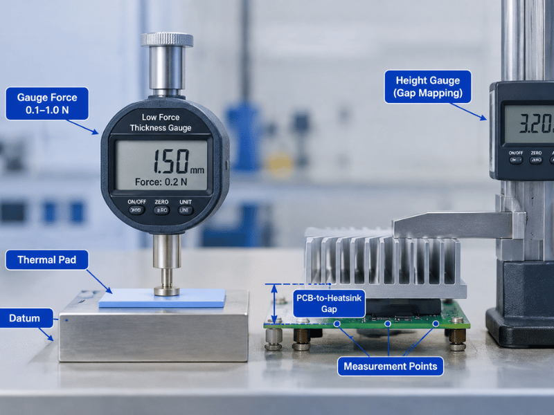
A standard digital caliper is convenient for firm materials, but its jaw force can compress a soft thermal pad. For incoming inspection, use a thickness gauge or micrometer with a documented contact foot and measuring force.
Record:
- Tool and asset ID
- Contact-foot size
- Measuring force
- Conditioning temperature and time if relevant
- Number and location of readings
- Acceptance tolerance
Measure away from damaged edges. For a large sheet, include the center and multiple corners. Report the range, not only the average; one thin corner can be the location that loses contact.
Jiuju reports standard thickness tolerance of ±10% and optional strict control of ±5% for thermal pads. Confirm the exact tolerance on the grade and drawing because capability can vary with formulation and thickness.
Method 2: Measure the assembled component gap
Establish datums
Start from stable surfaces used by the real assembly: mounting bosses, cold-plate datums, enclosure stops, or screw seats. Measuring two loose parts on a bench can miss the effect of gasket compression, board supports, and fastener load.
Reproduce the final mechanical state
Use the intended:
- Fasteners and washers
- Torque and tightening sequence
- Board supports and spacers
- Gaskets and seals
- Cooler, chassis, or lid
- Orientation if gravity affects the assembly
Map multiple points
Measure each thermal contact location and, for large components, more than one point per surface. A gap map should show minimum, maximum, and local tilt.
For a wide package, cold plate, or multi-component array, include the center, corners, and locations near fasteners or supports. One center reading cannot reveal surface bow or a tilted load path. If temperature materially changes the geometry, compare the cold assembly with a controlled hot-state measurement or validated deformation model. Record the temperature and fixture condition with the result; do not transfer a hot gap into a cold assembly calculation without that context.
The purpose is not to assign a generic thickness to a “large chip.” It is to discover whether one pad thickness can maintain contact everywhere without overloading the high points. If it cannot, evaluate zoned thicknesses, a more conformable grade, a segmented pad, or a different gap-filling method.
Recommended prototype methods include a height gauge or CMM, accessible feeler gauges, and non-hardening witness media. Select a witness material that does not spring back, contaminate the hardware, or require enough force to bend the board.
Do not install the thermal pad and then insert a caliper into the closed joint. That method usually measures an accessible edge, not the critical interface.
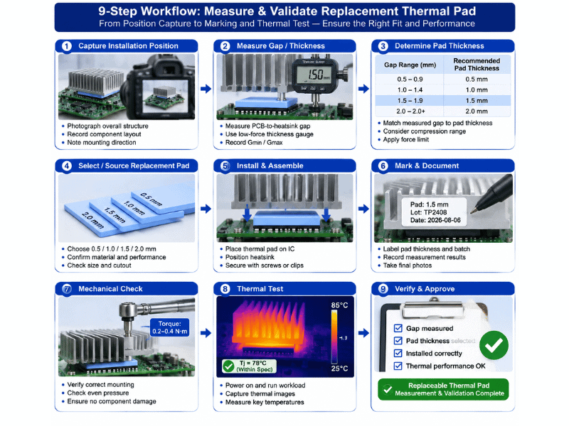
Method 3: Estimate an unknown replacement thickness
When no drawing or service specification exists:
- Photograph the unopened assembly.
- Label every pad location and orientation.
- Remove the cooler without stretching the pads.
- Inspect the contact print on both faces.
- Measure the least-deformed area with low force.
- Independently map the hardware gap when possible.
- Prototype nearby standard thicknesses.
- Reassemble at the correct torque and verify seating.
- Test temperatures under repeatable load and ambient conditions.
The old pad measurement is supporting evidence, not ground truth. Compression set, heat, and handling can change it.
Calculate Working Compression
If the free pad thickness is T and the installed gap is G:
Compression = (T − G) / T
A 1.5 mm pad compressed to a 1.2 mm working gap has 20% strain:
(1.5 − 1.2) / 1.5 = 0.20
Then compare that strain with the supplier’s compression-force curve. ASTM D575 is used to compare compression-deflection characteristics of rubber materials, but your design needs data for the exact pad construction.
Also check thermal data at relevant pressure and thickness. ASTM D5470 explains why measured thermal impedance includes interface effects and why a conductivity value alone does not describe the installed joint.
Build an Assembly Gap Map
For each location, record:
| Field | Example format |
|---|---|
| Location ID | VRM-03 |
| X/Y position | Drawing coordinates |
| Minimum gap | mm |
| Maximum gap | mm |
| Measurement method | CMM / witness / gauge |
| Sample size | Number of assemblies |
| Target pad grade | Supplier part number |
| Nominal pad thickness | mm |
| Calculated compression range | % min to % max |
| Force limit | kPa or N over contact area |
| Validation result | Pass / fail with report ID |
This table turns “looks about right” into a drawing input. It also makes supplier changes easier to evaluate.
Define QC Inspection Limits
Prototype metrology and production inspection should describe the same dimension. If engineering measures free pad thickness with one contact force while incoming quality uses a spring-loaded caliper with another, both teams can produce repeatable numbers that do not agree.
Write down at least:
- Instrument type and calibration status
- Foot diameter or contact geometry
- Applied measurement force
- Dwell time before reading
- Number and location of points
- Treatment of adhesive, carrier, texture and edge regions
- Sample quantity and acceptance rule
Jiuju’s documented laboratory list includes a thickness gauge, Shore 00 durometer, laser particle-size analyzer, compression tester and ASTM D5470 thermal tester. Each instrument answers a different question. The thickness gauge checks a dimension. The durometer checks indentation hardness. The compression tester shows force versus displacement. The thermal tester characterizes the heat path under defined conditions. One result should not be used as a shortcut for another.
For incoming raw materials, Jiuju documents checking filler particle-size points such as D10, D50 and D90, plus mixed viscosity and volatile content. Those upstream checks do not replace final pad measurement. They help explain why lot control begins before calendaring and die cutting: a formulation shift can change processability and mechanical response even when a finished coupon still looks normal.
Use a short measurement-system study before release. Have more than one operator measure the same marked locations, repeat the readings, and compare the observed variation with the drawing tolerance. If measurement variation consumes a large share of the tolerance, improve the method before rejecting production parts.
Common Measurement Pitfalls
- Squeezing a soft pad with a caliper
- Measuring only one corner
- Ignoring adhesive or carrier-film thickness
- Measuring an unfastened assembly
- Using an aged pad as the only reference
- Averaging away the maximum gap
- Forgetting board bow and cooler tilt
- Reporting compression percentage without pressure
- Comparing conductivity values tested under different conditions
Supplier RFQ Data Package
Send the gap map, contact area, fastener design, component pressure limit, operating temperature, electrical requirements, and contamination constraints. If the geometry is confidential, anonymized cross-sections and tolerance ranges can still support selection.
Jiuju reports that thermal-pad shipment reports can include conductivity, hardness, dimensions, appearance, and customer-defined critical tests. Ask for the measurement method and frequency in the quality agreement. The thermal pad specification table is a starting reference, not a substitute for the released drawing.
Next Steps: Sizing from Data
Accurate thermal pad measurement is less about buying a fancier caliper and more about defining force, datums, assembly state, and sample coverage. Measure the free pad for quality control. Measure the assembled gap for design. Use witness marks and temperature testing for validation.
Once the gap map is complete, compare 0.5 mm, 1 mm, 1.5 mm, and 2 mm pads or request help selecting a grade from Jiuju’s thermal pad range.