Yes, you can stack thermal pads in a prototype or repair when the required single thickness is unavailable. But stacking adds an internal interface, makes compression harder to predict, and creates more opportunities for layers to shift or trap contamination.
For production, one pad made to the required thickness is usually easier to validate and control.
What changes when pads are stacked
A two-layer stack is not always equivalent to one pad of the same total thickness.
An extra thermal interface
Heat must cross the contact between the two pad layers. Soft, tacky materials can make that interface small, but it is still another variable. Air, liner residue, dust, wrinkles, or poor contact can increase resistance.
Uneven strain sharing
If the layers have different hardness, thickness, or formulation, they may not compress equally. The softer layer can take most of the strain while the harder layer continues to load the assembly.
Lateral movement
Layers can slide during lid closure, vibration, or thermal cycling. Misalignment reduces contact area and can expose conductors or nearby parts.
Tolerance accumulation
Each layer has its own thickness tolerance. The stack’s minimum and maximum thickness range can be wider than expected.
For two identical nominal 1.0 mm layers at ±10%, the worst-case stack spans 1.8 to 2.2 mm. That is still ±10% of the 2.0 mm total, not ±20%. The problem is that you now have two measured parts, an extra interface, two opportunities for local thickness variation, and a layer-alignment process. If the layers come from different grades or tolerances, calculate each minimum and maximum separately.
Compare that with one nominal 2.0 mm pad. Jiuju reports a typical standard tolerance of ±10% and optional ±5% control, subject to exact-grade and order confirmation. One 2.0 mm pad at ±5% spans 1.9 to 2.1 mm and removes the pad-to-pad interface. That does not guarantee better thermal performance, but it gives production fewer variables to inspect.

When stacking may be acceptable
- Early prototype used to identify a workable total thickness
- One-off repair with no approved single-thickness replacement
- Low-risk, low-load assembly with full post-installation testing
- Temporary diagnostic step before ordering the correct part
Even then, use the same product family and avoid mixing unknown materials. Remove all protective liners between layers. Cut both layers to the same intended footprint and keep the stack flat.
When not to stack thermal pads
- Safety-critical or high-reliability production
- Large areas subject to vibration or shear
- Optical or contamination-sensitive enclosures
- High-voltage locations without verified insulation
- Assemblies with tight force limits
- Interfaces where cooler seating controls another critical TIM
- Automated processes that cannot verify layer alignment
How to test a stacked pad safely
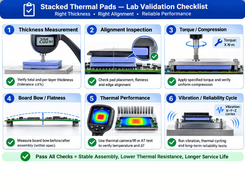
- Measure the real minimum and maximum gap.
- Measure each layer’s free thickness under controlled force.
- Add tolerance extremes, not only nominal values.
- Check the compression-force data for each layer.
- Assemble with the specified torque and sequence.
- Confirm hard-stop seating and board flatness.
- Inspect contact prints on the outer faces.
- Run controlled thermal testing.
- Reinspect after cycling or vibration relevant to the use case.
Record the individual lot numbers and layer orientation. A stack that passes one bench build is not production evidence unless the process can reproduce liner removal, cleanliness, alignment, compression and inspection.
For incoming control, do not approve the stack from its combined thickness alone. Measure each layer under the defined gauge force, then inspect the assembled stack for trapped particles, folds and offset edges. If the design depends on adhesive tack, identify which faces carry adhesive and confirm that the adhesive was included in the thermal and mechanical qualification. A receiving record should make it possible to trace both layers; otherwise one drifting lot can hide behind an acceptable combined reading.
Jiuju’s internal reliability menu includes high- and low-temperature exposure, damp heat, and thermal cycling or shock. Use only the conditions relevant to the product and application, with project-specific pass limits. After exposure, look for layer walk, edge extrusion, separation, cracking, changed contact print, board deformation and thermal-resistance change. A temperature reading alone may miss a stack that is mechanically migrating.
The complete thermal pad thickness guide explains the compression calculation. If the stack behaves as though it is too thick or too thin, stop and correct the geometry.
Does stacking double thermal resistance?
Not automatically. For identical material with the same total bulk thickness, the theoretical bulk resistance is similar. The stack adds an internal contact resistance that a single homogeneous pad does not have.
ASTM D5470 is helpful here because it distinguishes measured thermal impedance from apparent conductivity and recognizes interface resistance. A catalog W/m·K number cannot quantify an improvised pad-to-pad interface.
Better alternatives
Choose the alternative from the reason the stack was proposed:
- Only the required nominal thickness is unavailable: Order one pad in the validated grade and thickness.
- Component heights vary across the footprint: Use zoned pads, a segmented design, or evaluate a dispensable gap filler.
- The stack is meant to reduce temperature: First check contact, total bond-line thickness, and the rest of the heat path; another layer does not correct a system bottleneck.
- The stack compensates for cooler geometry: Correct the hard stops, spreader, shim, or support layout where practical.
This turns stacking into a diagnostic clue. It identifies whether the real selection problem is sourcing, topography, thermal resistance, or mechanical design.
Order one custom thickness
Jiuju reports custom thermal-pad thicknesses from 0.3 mm to 15 mm, with typical standard tolerance of ±10% and optional ±5% control. Confirm grade-specific capability and use one released construction when volume justifies it.
A single part number also simplifies receiving inspection, traceability and corrective action. Specify the controlled-force thickness method, critical die-cut dimensions, liner construction, placement orientation and shipment checks. If a field issue occurs, one released construction is easier to isolate than two independently variable layers.
Use a softer pad designed for the gap range
A more conformable grade may bridge the variation with less force, but check the exact compression curve.
Use thermal putty or dispensable gap filler
For irregular, multi-height, or wide gaps, a dispensable material may avoid a stack of sheet parts. It introduces its own controls: dispense volume, bond-line thickness, slump, pump-out, curing or pre-cure state, and rework. See Thermal Pad vs Thermal Putty for Uneven Gaps.
Redesign the mechanical interface
A stepped spreader, shim, pedestal, or changed mounting stop can reduce the gap without adding a thick compliant layer. This can improve both resistance and force control.
FAQ
Can I stack two 0.5 mm pads to make 1 mm?
You can for a controlled prototype or repair, but a single 1 mm pad is normally more repeatable. Validate contact, seating, and temperature.
Can I mix thermal pad brands or conductivity ratings?
Avoid it. Different hardness and compression curves make strain sharing unpredictable, and the lower-performing layer can dominate the stack.
Should I use thermal paste between stacked pads?
No by default. Paste can promote sliding, contaminate the assembly, and create an uncontrolled interface. Use only a supplier-approved construction with validation.
Does stacking increase electrical insulation?
Do not assume so. Layer shift, trapped debris, compressed thickness, and unverified dielectric behavior can undermine the design. Verify the complete stack.
Use stacking to learn, not to hide a missing specification
Stacked thermal pads can answer a prototype question: “What total thickness makes contact?” They are a weak substitute for a released production design.
Once the target is known, compare Jiuju’s thermal pad products and specify one grade, thickness, tolerance, die-cut, and inspection method.